Ductile Iron (also known as Spheroidal Graphite Iron or Nodular Cast Iron) was invented in 1949. Ductile Iron retains the corrosion resistance of cast iron but has more than double the tensile strength [Cast iron-180 Mpa (min), Ductile Iron-420 Mpa (min)]. The essential difference between Ductile and Cast Iron lies in the shape of the graphite in the microstructure of the metal. In Cast Iron, the graphite is present in plate-like flakes, which makes Cast Iron
brittle. But in Ductile iron, the shape of the graphite becomes a spheroidal nudule, which increase tensile strength and makes Ductile Iron sturdy and shock-proof.
Ductile Iron Pipe is considered as the most preffered pipe material for water supply and pressure sewerage application all over the world. It Offer higher Tensile Strength and diametral stiffness than Mild Steel and retains the inherent corrosion resistance of cast iron.
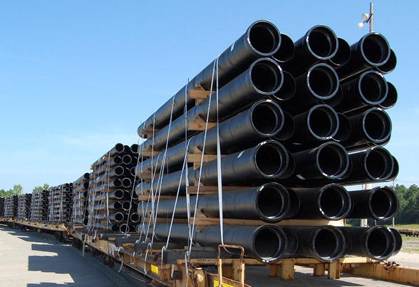
Pipes made from Ductile Cast Iron, provides substential benefits in terms of pressure bearing ability, impact resistance and capacity to sustain external static/dynamic loading.
| Properties | Ductile Iron Pipe |
| Tensile Strength | Min.420 MPa |
| Elongation (min) at Break | 10% |
| Elastic Coefficient | 1.7x10⁴ Kg/mm² |
| Modulus Of Elasticity | 1.7x10¹⁰ Kg/M² |
| Hardness | Max. 230 BHN |
| Density | 7050 Kg/M3 |
| Bending / Beam Strength | Over 50 Kg/M3 |
| Crush load and impact load | Can take up huge impact load (Charpy over 0.713). |
| Bursting Strength (min) | Factor of Safety against bursting is 8 to 10. |
| Size (DN) | Min. Hydrostatic Works Test Pressure (bar) | PFA (AOP) MAX (bar) | PMA (MOP) MAX (bar) | PEA (STP) MAX (bar) | ||||
| Class K7 | Class K9 | Class K7 | Class K9 | Class K7 | Class K9 | Class K7 | Class K9 | |
| 100 | 32 | 50 | 8 | 64 | 12.5 | 77 | 17.5 | 96 |
| 150 | 32 | 50 | 8 | 64 | 12.5 | 77 | 17.5 | 96 |
| 200 | 32 | 50 | 8 | 62 | 12.5 | 74 | 17.5 | 79 |
| 250 | 32 | 50 | 8 | 54 | 12.5 | 65 | 17.5 | 70 |
| 300 | 32 | 50 | 8 | 49 | 12.5 | 59 | 17.5 | 64 |
| 350 | 25 | 40 | 8 | 45 | 12.5 | 54 | 17.5 | 59 |
| 400 | 25 | 40 | 8 | 42 | 12.5 | 51 | 17.5 | 56 |
| 450 | 25 | 40 | 8 | 40 | 12.5 | 48 | 17.5 | 53 |
| 500 | 25 | 40 | 8 | 38 | 12.5 | 46 | 17.5 | 51 |
| 600 | 25 | 40 | 8 | 36 | 12.5 | 43 | 17.5 | 48 |
| 700 | 18 | 32 | 8 | 34 | 12.5 | 41 | 17.5 | 46 |
| 800 | 18 | 32 | 10 | 32 | 15 | 38 | 20 | 43 |
| 900 | 18 | 32 | 10 | 31 | 15 | 37 | 20 | 42 |
| 1000 | 18 | 32 | 10 | 30 | 15 | 36 | 20 | 41 |
| 1100 | 12 | 25 | 29 | 29 | 35 | 35 | 40 | 40 |
| 1200 | 12 | 25 | 28 | 28 | 34 | 34 | 39 | 39 |
For Class Pipes
| Size (DN) | C20 | C25 | C30 | C40 | C50 | C64 | C100 |
| 100 | - | - | - | 40 | 50 | 64 | 100 |
| 150 | - | - | - | 40 | 50 | 64 | 100 |
| 200 | - | - | - | 40 | 50 | 64 | 100 |
| 250 | - | - | - | 40 | 50 | 64 | 100 |
| 300 | - | - | - | 40 | 50 | 64 | 100 |
| 350 | - | - | 30 | 40 | 50 | 64 | 100 |
| 400 | - | - | 30 | 40 | 50 | 64 | 100 |
| 450 | - | - | 30 | 40 | 50 | 64 | 100 |
| 500 | - | - | 30 | 40 | 50 | 64 | 100 |
| 600 | - | - | 30 | 40 | 50 | 64 | 100 |
| 700 | - | 25 | 30 | 40 | 50 | 64 | - |
| 800 | - | 25 | 30 | 40 | 50 | 64 | - |
| 900 | - | 25 | 30 | 40 | 50 | - | - |
| 1000 | - | 25 | 30 | 40 | 50 | - | - |
| 1100 | 20 | 25 | 30 | 40 | 50 | - | - |
| 1200 | 20 | 25 | 30 | 40 | 50 | - | - |
| Standard Product | Ductile Iron Pipe Suitable for Push-on-Joint |
| Confirming Specification | ISO 2531; BS EN 545; BS EN 598 & IS 8329 |
| Class of Pipe | K7, K9, C20, C25, C30, C40, C50, C64 & C100 |
| Size Range | DN 100 To DN 1200 |
| Standard Length (in Meters) | 5.5 or 6.0 |
| Internal Linings | Cement Mortar Lining |
| Ouside Coatings | Zinc Coating (13gm/m² or 200gm/m² Alloy of Zinc And Aluminiumhaving a minimum mass of 400gm/m² Finishing Layer of Bitumen/Blue Epoxy/Red Epoxy |
| Outside Onsite Protection | Polyethlene Sleeving |
| Confirming of Joint Area | Bitumen/Epoxy |
Nominal Diameter, External Diameter and Wall Thickness
| Nominal Diameter (DN) in mm | External Diameter (DE) in mm | Tolerance on External Diameter | Minimum Barrel Wall Thickness (e) | ||||||||
| K7 | K9 | C 20 | C 25 | C 30 | C 40 | C 50 | C 64 | C 100 | |||
| 100 | 118 | +1/-2.8 | 3.7 | 4.7 | - | - | - | 3.0 | 3.5 | 4.0 | 4.7 |
| 150 | 170 | +1/-2.9 | 3.7 | 4.7 | - | - | - | 3.0 | 3.5 | 4.0 | 4.7 |
| 200 | 222 | +1/-3.0 | 3.7 | 4.8 | - | - | - | 3.1 | 3.9 | 5.0 | 7.7 |
| 250 | 274 | +1/-3.1 | 4.0 | 5.3 | - | - | - | 3.9 | 4.8 | 6.1 | 9.5 |
| 300 | 326 | +1/-3.3 | 4.3 | 5.6 | - | - | - | 4.6 | 5.7 | 7.3 | 11.2 |
| 350 | 378 | +1/-3.4 | 4.7 | 6.1 | - | - | 4.7 | 5.3 | 6.6 | 8.5 | 13.0 |
| 400 | 429 | +1/-3.5 | 4.6 | 6.4 | - | - | 4.8 | 6.0 | 7.5 | 9.6 | 14.8 |
| 450 | 480 | +1/-3.6 | 4.9 | 6.8 | - | - | 5.1 | 6.8 | 8.4 | 10.7 | 16.6 |
| 500 | 532 | +1/-3.8 | 5.2 | 7.2 | - | - | 5.6 | 7.5 | 9.3 | 11.9 | 18.3 |
| 600 | 635 | +1/-4.0 | 5.8 | 8.0 | - | - | 6.7 | 8.9 | 11.1 | 14.2 | 21.9 |
| 700 | 738 | +1/-4.3 | 7.0 | 8.8 | - | 6.8 | 7.8 | 10.4 | 13.0 | 16.5 | - |
| 800 | 842 | +1/-4.5 | 8.3 | 9.6 | - | 7.5 | 8.9 | 11.9 | 14.8 | 18.8 | - |
| 900 | 945 | +1/-4.8 | 9.0 | 10.4 | - | 8.4 | 10.0 | 13.3 | 16.6 | - | - |
| 1000 | 1048 | +1/-5.0 | 9.7 | 11.2 | - | 9.3 | 11.1 | 14.8 | 18.4 | - | - |
| 1100 | 1152 | +1/-6.0 | 12.0 | 12.0 | 8.2 | 10.2 | 12.2 | 16.2 | 20.2 | - | - |
| 1200 | 1255 | +1/-6.2 | 12.8 | 12.8 | 8.9 | 11.1 | 13.3 | 17.7 | 22.0 | - | - |
| Types of cement | Usage | Conforming to |
| Portland Cement/Blast Furnace Cement | Drinking water having pH 6.0 to 9.0 | ISO:4179 BSEN:545 |
| Sulphate Resisting Cement | Raw water/Sea water/Non septic sewers water | ISO:4179 BSEN:545 |
| High Alumina Cement | Surface water/Domestic waste water/Certain types of industrial effluents | BSEN:598 |
| Reference Specification | Size range (DN) | Cement lining thickness in mm | Maximum crack width & radial Displacement (mm) | |
| Nominal | Minimum at one point | |||
| BSEN 545 | 80-300 350-600 700-1200 |
4.0 5.0 6.0 |
2.5 3.0 3.5 |
0.40 0.50 0.60 |
| ISO 2531 ISO 4179 |
80-300 350-600 700-1200 |
3.0 5.0 6.0 |
2.0 3.0 3.5 |
0.80 0.80 1.00 |
